GCP2 calculates for both normal and transverse planes. ‘GCP2’ Ash Gear’s own gear calculation software. Software for the Gear Manufacturer.
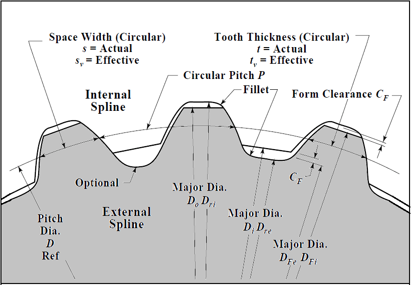
Splines 1989 similar to din 5480 but, the module allows a fast and easy calculation of the geometry and strength of.The Spline Calculator software allows for a quick and uncomplicated calculation of the spline data and inspection dimensions of internal and external. This new tool promises to provide:Spur and Helical gear calculator. For the upcoming July update, we’re extremely excited to introduce a brand new way to create curves in Fusion 360’s sketching environment – the Control Point Spline tool. Calculate root produced when tooth. Calculate T.I.F and roll angles using your existing tooling. Contact scottashgear.com for more information.
More precise shape control over your spline curves The following formula will work for any GM, Ford or Chrysler vehicle and is very useful when there is no. Formula for Calculating Speedometer Gears. The Spline Calculator is a hands-on tool to slowly approach the required tooth shape and the most suitable measuring circle.

Spline Calculation Tool Series Of Points
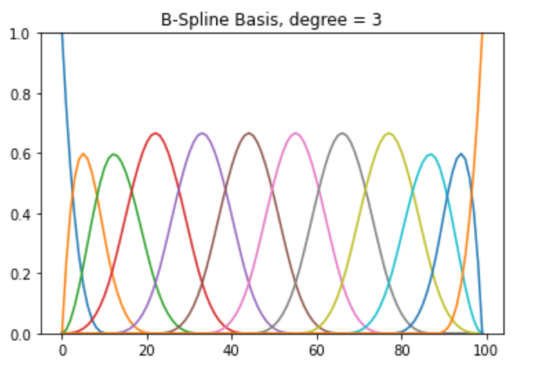
These are now presented in a Spline flyout in the Sketch tool menu.As you start to use these two tools together, there are two key differences to keep in mind between fit point splines and control point splines:1. The spline ‘fits’ to the specified points). You select a series of points, and these points will define a ‘control frame’ from which a smooth curve is derived.If you’ve ever used Box Display or Control Frame Display in the Sculpt workspace, you’re essentially seeing the same concept there: you manipulate a simple polygonal control frame, and this drives the resultant smooth shape of the surface.Since we’ll now have two spline commands, we’re renaming the previous Spline tool to “Fit Point Spline” (i.e. With this tool, you select a series of points, and Fusion will create a smooth curve that passes through them.Control point splines offer an alternative approach for achieving the same result. What does the Spline Degree control do?Control point splines – also known as CV splines, NURBS curves or style splines – provide a way for defining complex curves in a Sketch.Until now, this requirement has been met by the existing Spline command.

Spline Calculation Tool Full Shape Of
Fit point splines provide tangent & curvature handles to apply additional control if needed but occasionally these don’t provide fine-enough control, and manipulating these handles can affect other areas of the spline in unexpected ways.Control point splines give you direct access to the underlying control points that define the full shape of the curve. However, behind the scenes Fusion is taking most of the responsibility for deciding how the spline shape flows as it passes from one fit point to the next.As a product designer, sometimes you need to have very precise control of that intermediate shape flow. In such cases, adding more control points as needed is the required approach to achieving more flexible shape control.Fit points are a very intuitive way to define a spline – the points you create will directly constrain the curve. A control point spline with three points will feel much more rigid, and the lack of tangent/curvature handles limits the types of shape change possible. A fit point spline with three points will feel very flexible, and can be easily manipulated into a variety of shapes. What’s more, control point splines do not offer tangent/curvature handles to apply more refined shape control, you’ll need to add more points (you can do this by right-clicking the spline and selecting Insert Spline Control Point).For an example of this, see the two curves below.
Creating unnecessary intermediate points means you are ‘overriding’ that natural smoothness, which increases the potential for undesired bumps or wobbles in the curve.The general rule here is “less is more”. Use the fewest points possible to describe the shape you needSplines will naturally form the smoothest transition possible between two points. An example of this would be a traced logo: for a small & detailed design task like this, the high degree of mathematical smoothness provided by control point splines is probably less important, and the shape can be created and edited with much less work using a fit point spline.However, for many tasks the choice of spline tool is really a personal preference – while control point splines offer more flexibility for certain scenarios, the two tools fundamentally create the same type of geometry, so you may just gravitate towards one particular tool that suits you best!What are best practices for using control point splines?There are a few core rules of thumb to follow in order to create high-quality curves with the Control Point Spline tool.1. They provide you the ability to very explicitly control the math of the surface and by following the best practices discussed below, you can ensure that surfaces created from these splines will be both aesthetically and technically smooth.However, since a control point spline will require more points than a fit point spline to define a given shape, complex shapes with lots of curvature changes may be simpler to draw with the Fit Point Spline tool. Whether you prefer the interaction of creating fit point splines or control point splines is really down to your previous experience and personal taste – but control point splines offer a clear advantage in the level of shape control they provide.The classic school of thought is that control point splines are better than fit point splines for defining the primary surfaces of your model.
Keep adjacent points relatively close to each otherAvoid having drastic distances or direction changes from one control point to the next – this results in splines that will be difficult to work with or adjust later on. But keep in mind that, where you have transitions from spread-out control points to bunched-together control points, make sure those transitions are smooth and natural to maintain a high-quality curve.3. There are scenarios where you need to have control points more bunched-together in certain areas – namely, in areas where you want a higher-curvature shape. Try to keep points evenly-spaced where possibleUneven control point distribution is another factor that can cause smoothness problems in a spline, so wherever possible keep the spacing between adjacent control points even. In this case, adding one or two more control points can provide a more suitable level of shape control.2.
Constraints used to describe a relationship between the spline to other geometry are best applied on the curve itselfThe most frequently-used constraints for describing a relationship to other geometry will be Tangent and Curvature constraints: these will build a smooth connection between a control point spline and another curve or edge on the model.One important rule for applying tangent or curvature constraints on control point splines is that you will need enough ‘free’ control points for the constraint to succeed. Constraints used to control the overall size and shape of the spline are best applied on the control frame To make the most of this, Fusion 360 allows you to apply constraints on both the control frame and the curve itself. Combining these two methods can open up some unique and powerful constraint workflows.Since the control frame consists of straight lines, and the curve itself is a shape with complex curvature, different constraint types will be more meaningful on the two different object types.
This is because, when you apply the constraint, Fusion will need to shift that control point to a new aligned position that enforces the tangent relationship.


 0 kommentar(er)
